1994-2002 [Subscribe to Daily Digest] |
 Members do not see ads below this line. - Help Keep This Site Online - Signup
It has been a couple of weeks, but here are the dirty details. See links at end for rear Koni install and SAS rear sway bar and DIY alignment. If you have a manual, print this off and keep it there.
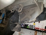
Koni front shock install details
drs_install <-- search key word
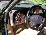
Subject vehicle: 95SET, manual gear box, alloy wheels, 130000 miles
Viggen Rescue Kit, SAS rear sway bar
original front rotors and pads
Problem: The suspension had started to hit the travel stops. Reduced tire pressure from 38F35R to 33F33R and then after a couple of months the same problem. The vehicle never seemed loose when trying the rock or bounce tests by pushing on the vehicle.
State of the old shocks. With 130000 miles there was no leakage on the front or rear shocks. When removed pushing them in by hand did not disclose any gross obvious lack of action. Others have reported that old shocks appeared to have no dampening resistance. The old shocks were allowing some fast lane change steering dynamics which were nasty. Body roll dynamics were affecting steering geometry. The subject vehicle has the Viggen Rescue Kit which may have focused these affects that might not be an issue on a stock system.
Have another vehicle at hand in case you need to get tools or supplies during the job.
Tools required:
wide (2.5" gap) jaw putnum puller for the tie rods ends, or a 2 arm gear puller, if you have neither, get the two are puller has you may have more use for it down the road.
workbench with a large vice
some motor oil or full strength antifreeze and a ability to measure 2oz or 50ml (50cc).
16mm 1/2" socket
15/16" socket
13mm hex socket and open ended wrench
11mm open ended wrench and perhaps a socket as well.
16mm open end and close end 12 point combination wrench
1 & 1/4" 12 point 1/2" drive socket. Not an impact socket, wall would be too thick!
10mm hex bit for 1/2: drive or 3/8" with 1/2 to 3/8 drive adapter
5mm allen key
1/2" drive torque wrench for over 200 ft-lbs
#40 torx drive, bit or key
two hydraulic floor jacks
hammer
6 ft long lever, a 2x4 would be ideal
heavy coat hanger wire to make hangers for calipers
spring compressor, one kit consists of two compressor units for one spring
a pin wrench with 5.5 to 6.0 mm pins for 39mm center to center. Commonly known as a face pin spanner. If you don't have one, you can use a chain wrench or large water pump pliers.
The instructions from Koni are cryptic. No words, just pictures. That way they do not have to produce in N laguages.
So this is how I did it. I used Baab's posts as a guide. Don't bother searching for them, they do not exist anymore.
1) Remove hub caps if equipped. Use the a 1 & 1/4" socket and 1/2 drive breaker bar to loosen up the nut on the spline end of the drive shafts. You can safely remove the nuts at this time. Loosen the wheel mounting bolts. You may have to drive the socket onto the nuts with a hammer. A close fit!
2) Jack up the front of the vehicle on both sides and remove the wheels. Now fully remove the 1 1/4" drive shaft nuts if not already done. If the brakes are needed, they are still operational at this point. But that would require an assistant.
3) Remove one 5mm hex alan head screw on each brake rotor, turning the steering wheel to expose if neccessary, remove one 5mm hex alan screw for each ABS senor, and suspend behind the sway bar to keep out of harms way.
4) Loosen the 3 13mm hex nuts at the top of the strut. DO NOT remove the 11/16 nut on the top of the shock piston shaft. You may loosen it to break it torque only to make later work easier. You can use a 13mm OE wrench at this point to secure the shaft while using a 11/16" OE wrench.
5) Remove the two 10mm alan cap bolts from each caliper and remove the caliper from the hub and hang from the steel brake line mounting bracket ensuring that there the rubber brake line is not taking a load. You will need a 1/2" breaker bar to get things going and finish with a rachet wrench. The bolt has locktite and will not spin out on your fingers. Clean out the 10mm hex cavities in the bolts before attempting to remove. Make sure the hex drive inserts fully as to not damage the fastener.
6) Optional: you can remove the brake splash shields to get more room to work. The shields are easily removed and replaced, IF the 3 #40 torx screws are able to be moved. So if you cannot get all three to break free, tighten up any that moved and skip this operation. Clean the torx cavities of the screws to remove rust and dirt before attempting. An air compressor and blow gun is useful at this time.
7) Remove the tie rod end 16mm nuts. Try a moderate hammer blow on the end of the tierod after the nut is fully removed. Do not damage the threads. If this does not release the tapered joint, use the 2 jaw gear puller or large putnam removal tool. Oil the tie rod adjuster clamp screws and adjuster threads (large) at this time for preventive maintenance. Oil also via the sawcuts in the clamps as well.
8) Remove the sway bar from the control arm. Use a 11mm OE wrench up top to secure the fastener as you remove the lower 13mm bolt with a socket wrench. Set aside the nut, curved washer and lower half of the split rubber bushing.
9) Remove the 16mm nut for the ball joint using a OE wrench. There is no room for a socket. Turn the strut to get best access, especially if you left the splash shields on.
10) This is the most tricky part of the operation. There is no room for a commonly availble tool. (Perhaps you should attempt this part before other items as much as possible. If you cannot separate the ball joint tapered connection, you will have to give up and put everything back.) I drove wedges against the end of the threads and the drive shaft constant velocity joint housing... which is very heavy. Baab managed to use a cold chisel as a wedge. but you have to avoid cutting the rubber boot! My dealer mechanic states that they do not use a tool as uou would expect, but put some force on the control arm to pull down on it a bit, not being too forceful, and then with the strut fully turned to get a good exposure, with the spach shields still on!, they then give the hub a good whack with a hammer right at where the tapered joint is, and they get the joint to pop open. I wish I had known to do that. So a good weight steel hammer is needed. I am sure that they have a technique that will be hard to duplicate. But if this works, it should be fast and easy.
11) Remove the 1 1/4 drive shaft nut now if not fully removed earlier.
11) Now lever the control arm down using the subframe for a fulcrum. This is where the 2x4 will be used. 6 or 8 feet long does not matter, as long as you have clearance to the side to use it. Move the control arm down to get the tapered pin free of the hub. Move the strut and hub out to then let the control arm back up and remove the lever.
12) Remove the inboard 13mm nut at the stut top to allow the strut to pivot on the two outermost loosened nuts. Watch where the washer(s) are. There are not three. Place the nuts and washers in a safe location!
13) Now the strut is easily pulled to the side from the hub. Pull it out a bit and confirm that the spline will move. If it will not, get the hammer and persuade it. Now pull the strut out to clear the spline WHILE holding the shaft back to keep it form comming out of the transmission (which is not a good thing). Find a location where the shaft will lie down on the control arms which will keep it from comming away from the transmission. Some movement of the shaft from the transmission is ok.
14) Reach down and grab the strut by the spring and with your other hands, sorry, you need to put down the beer, remove the two other 13mm strut top nuts and watch for the washer(s)! Now remove the strut from the vehicle.
15) Install the spring compressor and cpmpress the spring. Follow the manufacture's instructions and safety notes.
16) Remove the 15/16" nut on the shock shaft using an open ended wrench and an 11mm box wrench or socket to constrain the shaft if needed.
17) Remove the large curved washer, the mount, bearing, another curved washer and spring seat. The top rubber spring seat will stick to the top spring seat. Now remove the bump stop and bellows from the shaft.
18) Put the large steel hex nut on the strut top it a vise and find a way to turn the strut. Or put the strut into the vise and use a large wrench to undo the nut. Remove the nut and old shock. Clean out the strut tube if not clean.
19) Put 50ml or 50cc of oil or antifreeeze into the strut tube to facilitate heat transfer, then insert the new shock, tighen the Koni supplied retaining nut with a an adjustable face pin spanner or improvise. The nut will not thread fully in.
20) Place the spring back on the strut noting how it should locate to the lower spring seat. Slide on the bump stop, and upper spring seat. Note how it lines up with the detail at the end of the spring. Now the lower washer, curved side up to the rubber of the mount and partnumbers down, now the mount with the top washer again curved side to the mount rubber. Put on the Koni supplied lockwassher and nut. Tighen down firmly. Final torque can be done later.
21) Put strut top into the shock tower loosely fitting the two outboard nuts only. Put a washer below the nut that does not ride on the shock tower brace.
22) Pull the bottom end of the strut out too allow the spline shaft to insert into the hub as the strut is pushed back. Do not pull the drive shaft out of the trany!
23) Lever down the control arms and then guide the ball joint pin into the tapered hole of the hub. Engage the 16mm ball joint nut before the shaft is fully inserted. Insert the front sway bar end into the control arm. Remove the lever. Place the lower 1/2 bushing on the sway bar end from below, and the washer curved side to the rubber, torque the nut to 7 ft-lb using a 13mm socket below and a 11mm open ended wrench above to restrain it.
24) Engage the tierod end and torque to 44 ft-lbs. You mau need to drive the tie rod end down to develop enough friction to run the nut on. Put some wood blocks under the ball joint and lower the vehicle to create a load on the tapered pin. This will develop enough friction to tighten the 16mm nut. No room for a socket and torque wrench. But you could use a 16mm crows foot. Restore the jacked up height and remove the wood blocks.
25) Use a 5 mm allen key to mount the ABX sensor. Use anti sieze. Fit splash guards, #40 torx, if previously removed, use anti seize.
26) Fit rotor and its retaining screw, 5mm hex, use anti sieze. Fit the caliper with the two 10mm cap bolts and torque to 78 ft-lb for 1994 thru 1996 and 81 ft-lb for 1997 and onward.
27) Fit the third strut top 13mm nut and run them down loosely.
28) Run on the 1 1/4" spline shaft nut.
29) Mount the wheel and partly tigten the wheel bolts.
30) Lower the vehcile onto the tire. Torque the spline shaft nut to 214 ft-lb. Torque the road wheels, move the steering wheel back and forth a few times to allow the top of the strut to bead down and torque the 3 13mm nuts to 13 ft-lb. Torque the shock shaft 11/16" nut. There is no provision to stop the shaft from moving...
31) After both sides are done, road test and adjust the toe in and steering wheel center if needed.
See my post on DIY alignment.
http://www.saabnet.com/tsn/bb/NG900/index.html?bID=51799
Rear Koni shocks were installed here:
http://www.saabnet.com/tsn/bb/NG900/index.html?bID=50905
SAS rear sway bar was installed here:
http://www.saabnet.com/tsn/bb/NG900/index.html?bID=49446
posted by 208.24.17...
No Site Registration is Required to Post - Site Membership is optional (Member Features List), but helps to keep the site online
for all Saabers. If the site helps you, please consider helping the site by becoming a member.
 |
 |
 |
 |
 |