1999-2009 [Subscribe to Daily Digest] |
 Members do not see ads below this line. - Help Keep This Site Online - Signup
The motor was chattering when actived and non-fuctional.
Removed the unit as described in posts by others.
The unit is difficult to open up. It is held in place by four plastic pegs that snap into the outer grey cover. It seems impossible to pry and release all four at once to slide the guts out. With four strips of metal forced between the cover (grey -seems to be polypropylene and the inner part (white nylon). I used a chisel to crack the cover from the sides, between the hole and the corner, then the flaps can be lifted and the guts slid out.
The metal role pins in the pegs do not need to be removed.
First remove the gator/boot from the yellow end unit, and force it to slide out sideways. Note the orientation. With that was inserted into a slider and though that you can see the end of the white frame, same piece exposed at the other end. I pushed on that end to get the frame to slide out.
When you get it out, take a digital picture like you did before pulling it out of the tailgate.
The inner parts are all nice colors, looks like fisher price.
Lift off the slider. Note the orientation of the white piece threaded onto the jack screw.
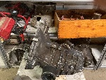
What breaks: The motor's pinion gear drives a nylon gear that turns a plastic jack screw. That jack screw fails and appears to be the expected torsional overload shear failure.
To remove the jack screw, pull it out as you bend the white nylon frame. Note how the white gear fits the jack screw and the location of the spacer that fits over the jack screw.
I drilled a 1/8" hole into each end of the busted jack screw and stayed clear of the ends, a pin and a socket. Drilled a very small hole in from the sides to intersect with the ends of 1/8" holes. Cut a 1/8" steel rod to fit into the length of the combined hole. Put that rod into an electric drill and file the outside to rough it up with a course file and with the corner of the file, scarred the rod deeply.
Mixed JB-Weld and packed into the holes, the vents at the end now come into play. Coat the end of the degreased rod and push into the short plastic piece until bottomed. The repeat for the other end. If the holes are centered and straight, the jack screw will go together straight. That is the part that many will find impossible to do. Let the JB-Weld set for 24 hours and reassemble and install.
I don't know if the JB-Weld will stick to the drilled hole. Time will tell.
The frame is obviously equipped for electrical limit switches that Saab elected to not use. I think that this leads to the overload of the jack screw. The jack screw appears otherwise to be weak and not a suitable material for this design/configuration. It appears to be a self lubricating plastic that might also be weak.
No Site Registration is Required to Post - Site Membership is optional (Member Features List), but helps to keep the site online
for all Saabers. If the site helps you, please consider helping the site by becoming a member.
 |
 |
 |
 |
 |